"Differentiating the sound of engine detonation from the noise of valves opening and closing, pistons rising and falling,
cam chains clanking and general under-bonnet noises has proved to be the hardest part of detecting when detonation is occurring.
One way to reduce this problem of sorting the wheat from the chaff is to decrease the time for which the sensor is actually
listening. The major noise of detonation for a specific cylinder occurs from shortly after the piston reaches Top Dead Centre on
its power stroke to between 60 - 90 crankshaft degrees later. If the detonation signal is allowed pass through to the detection
circuit and be averaged only when each piston is in this position, the accuracy of detonation detection improves. Crankshaft
position sensing then obviously becomes an important part of this approach.
The signal developed by a sensor is processed so those signals that (hopefully!) aren't detonation are filtered out. This
is achieved by the use of an approximately 10KHz wide bandpass filter. Beyond the bandpass filter the signal is commonly split
into two paths - one branch going on to become an averaged reference signal, with the other signal compared with the reference
only during the periods when each piston is in the right position for accurate detonation sensing. A 'detonation
detected' outcome leads to a retard in ignition timing in most factory engine management systems."
The article then provides a formula for computing the knock frequency:
frequency = 900 / (3.15 * cylinder_radius)
Where the cylinder radius is in meters.
For a TR6 this equates to 7670 Hz. Nice equation but read on and we will bust this myth.
So Much For Theory - The Real World Knocks
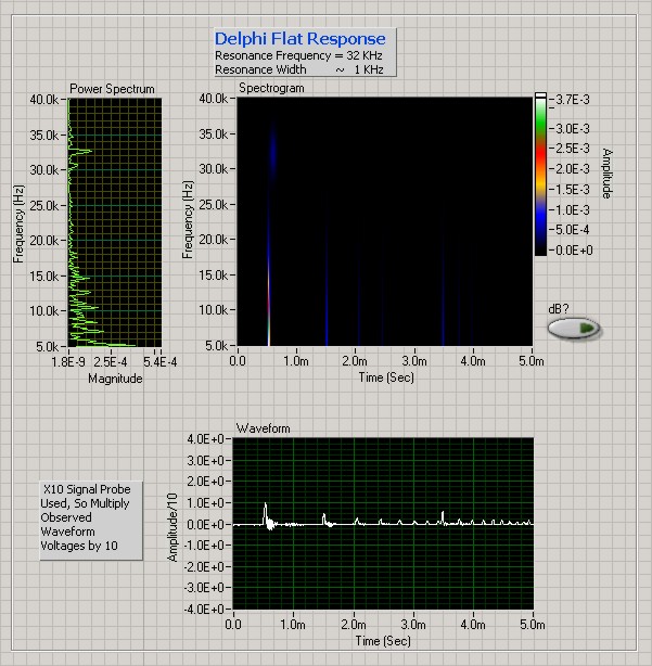
I mounted a Delphi Flat Response Knock Sensor on a '74 TR6 and recorded engine knock at a 44.1 kHz sampling frequency.
Delphi specifies a sensor frequency range of 1 to 18 kHz; Labview FFT shows a cutoff frequency of 15 kHz.
Big Moose's frequency response diagram confirms sensor rolloff at about 15 kHz but also includes a resenance above 30 kHz. In
the future I'll exclude these frequencies via a bandstop filter.
The numbers and figure is simply geek-speak to say that the data and results are valid.
Audio Recording of Delphi Sensor Output
The following is a short MP3 recording of the Delphi sensor when my TR6 is knocking: TR6 Knock (118 kB)
Here is a longer recording that includes both knock free and knocking periods: TR6 Knock (1,226 kB)
This later recording is the data used to generate the following FFT plots via Matlab. Plesae feel free to play with it and see
if you can detect the knock.
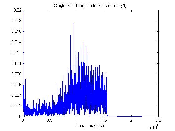
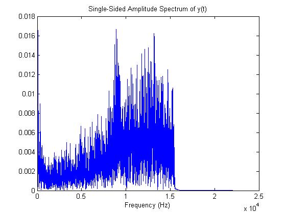
Knock Sensor FFT - No Knock
The audio data has been processed by a Fast Fourier Transform to generate a spectral response. The graph shows the magnitude
of the audio across the frequency spectrum. This a "typical" engine frequency response without any knock. The noise is
spread over a wide range of frequencies with a maximum amplitude at about 11 kHz. Based on my observations the engine frequency
response can change significantly over a short period time.
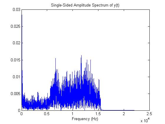
Knock Sensor FFT - Knock at 6.8 kHz
This shows a very strong knock centered at 6.8 kHz. The important issue here is that the knock signal is spread out across the
spectrum and raises the base noise level as well as generating a spike at 6.8 kHz. A very sharp bandpass filter will reject a
significant amount of energy and a wide bandpass filter will allow a significant amount of background noise through.
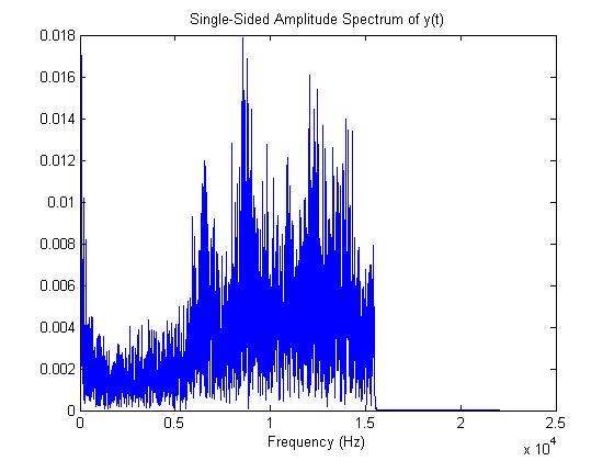
Knock Sensor FFT - Knock at 6.8 and 9 kHz
This shows a very strong knock at both 6.8 and 9 Hz. Again we notice that the overall background noise increases, however, in
this case the spikes are higher in amplitiude and easier to filter. There is also a small resonance at about 12.2 kHz.
Knock Sensor FFT - Knock at 9 kHz
This shows a very strong knock at 9 Hz. Notice the complete lack of signal at both 6.8 kHz and 12.2 kHz.
Summary
Unfortunately the equation that predicts the knock frequency at 7670 is a little off. Audio signatures indicate the TR6 engine
has resonance frequencies at 6.8 and 9 kHz, unfortunately, the signatures may not occur simulaneously. Using Labview I could
easily construct high order digital filters at 6.8 and 9 kHz and wire them together in different configurations to detect knock.
Due to the fact that the knock signal can be completely absent from one or the other frequencies it is difficult to generate a
filter that will detect knock all of the time.
My final conclusion is that continuous frequency filtering alone is not sufficient to assure knock detection. As a result I am
currently updating my recording system to include a signal for top dead center (TDC). With this information I can split the
signal and only detect knock immediately prior to TDC which should help improve the signal-to-noise ratio.